
The project involved demolition of an existing crescent building to construct a super-prime residential development opposite Regents Park in London. It is well summarised by the structural engineer, AKT here, the architect, PDP London, here and the acoustic consultant, Hilson Moran here. Demolition was carried out by McGee, the concrete frame was constructed by JRL Group who installed the bearings. Mid way through our contract Midgard took over as main contractor who carried out the high specification fit out.
Regents Crescent
London, United Kingdom
Industry
Construction
Sector
Urban Living
Building Type
Residential
Building Elements
Concrete Frame, Steel Frame, Heritage Façade, Super Prime Residential
The Project
Key value we brought to the project
A highly complex project which Farrat worked through every detail to end up with a well-constructed acoustically isolated building. The whole system was manufactured by Farrat in the UK, delivered on time followed by significant installation support and inspection services all leading to a successful outcome.
Services, Products, System Supplied:

For Farrat the project started back in 2014 when it was referred to as Park Crescent West. We started detailed design work with AKT II from June 2015. Even though not a high-rise development it was always going to be a challenge because of the size of the building and the variety of conditions across the site. The main building split into 3 zones, zone 1 to the left, zone 2 in the middle and zone 3 to the right and zone 4 is the mews properties at the bottom
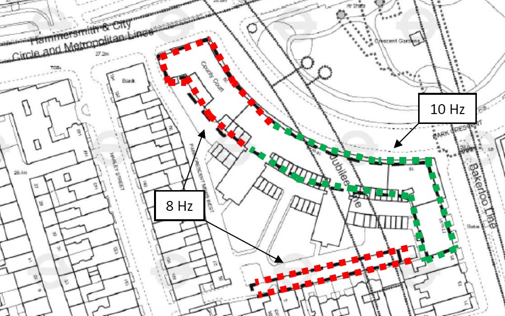
Hilson Moran were commissioned by the client to provide the acoustic specification. The image (an exert from the Hilson Moran report) shows the site affected by three London Underground (LUL) lines, Hammersmith & City Line,
Circle Line and Metropolitan Line to the north, The Bakerloo Line to the east, and the Jubilee Line which runs underneath the site, from north to south.
The proximity and level of groundborne noise from each line led to the performance specifications of 8Hz (zones 1 & 4) and 10Hz (zones 2 & 3)

It was decided (unlike most projects nowadays, Farrat was not involved in this decision) to isolate the entire structure below the ground floor slab leaving the basement un-isolated apart from certain areas that required box-in-box solutions. This structural model, courtesy of AKT II, nicely shows the different aspects of the structure including capping beam, cores, columns and the steel framed mews structure.

Basic schematic of the building vibration isolation scheme used at Regent’s Crescent, isolated under ground floor allowing for a standard basement construction except at ground floor where acoustic bearings are required to resist the soil pressure around the capping beam. This system also splits the cores mid-span meaning a lift manufacturer had to be selected who could accommodate this.

This image taken during the basement excavation, sums up well the scale and location specific challenges of the site.

And here, looking through the small section of retained façade (that we will come to later) from the site offices into the basement excavation.
Perimeter Capping Beam
A capping beam is a structural element that ties all the perimeter retaining wall piling together. In Regents Crescent there were multiple scenarios and details around the site but the majority were based on the principle that the incoming soil pressure forces would pass through the ground floor slab and be cancelled out by the forces on the opposite side of the building.

Here is an example of a detail where 50mm thick Farrat Isofoam was installed against the capping beam vertical wall and the ground floor slab was cast up against it. This makes for a neat detail that is easy to construct, won’t allow dirt and debris to fall into the isolation line and bridge the system and prevent groundborne vibration passing though it. The lateral forces were resisted by high capacity Farrat Hybrid Bearings set into the Isofoam in strategic locations, typically every 1 to 2 meters.

This photo was taken at a convenient time to see the black Isofoam between the vertical capping beam wall and the end of the ground floor slab.

In Zone 4, on the right side of the building opposite the mews building there was no opposing capping beam or core meaning the shear forces from the soil pressure had to be resisted within the capping beam. For this we used our bearing assembly configurator to design a high capacity one way shear key that could be post-fixed to the capping beam.

Site photo of the Zone 4 capping beam with two Farrat one way shear keys during installation. The photo shows the complexity of the overall build-up that all needs to be factored in to design and construction to ensure that the acoustic isolation line is not compromised.
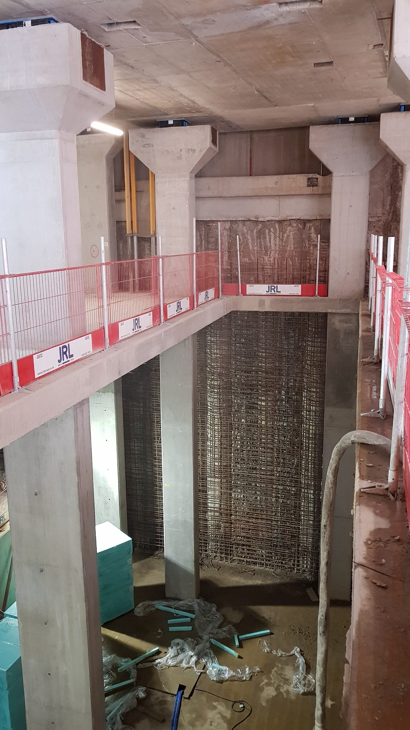
Cores & Shear Walls
The cores accommodate lifts and staircases and together with shear walls provide all of the lateral restraint for the building. Since the cores were to be split under ground floor level this posed an additional challenge as the Farrat LNR Bearings used to support and acoustically isolate the structure are wider than the walls. LNR Bearings are manufactured with natural rubber which has a high bulk modulus meaning it maintains its density even when compressed resulting in bulging around the outside of the bearing. This means that larger bearings have relatively higher capacity than smaller bearings and therefore 1x large bearing (e.g. 500x500mm) will have significantly more vertical capacity than 4x 250x250mm bearings with the same build-up.

As you will see from the photos, we used a combination of large bearings (wherever possible at the ends of walls and corners to minimise rotation in the structure) and smaller bearings that fitted neatly within the walls. Where larger bearings were used the walls had to be flared out in order to accommodate the acoustic bearings.

View along a stair core wall with 250x250mm Farrat LNR Bearings supporting the building above. This photo was taken at an early stage of the build so the bearings are not under much load.

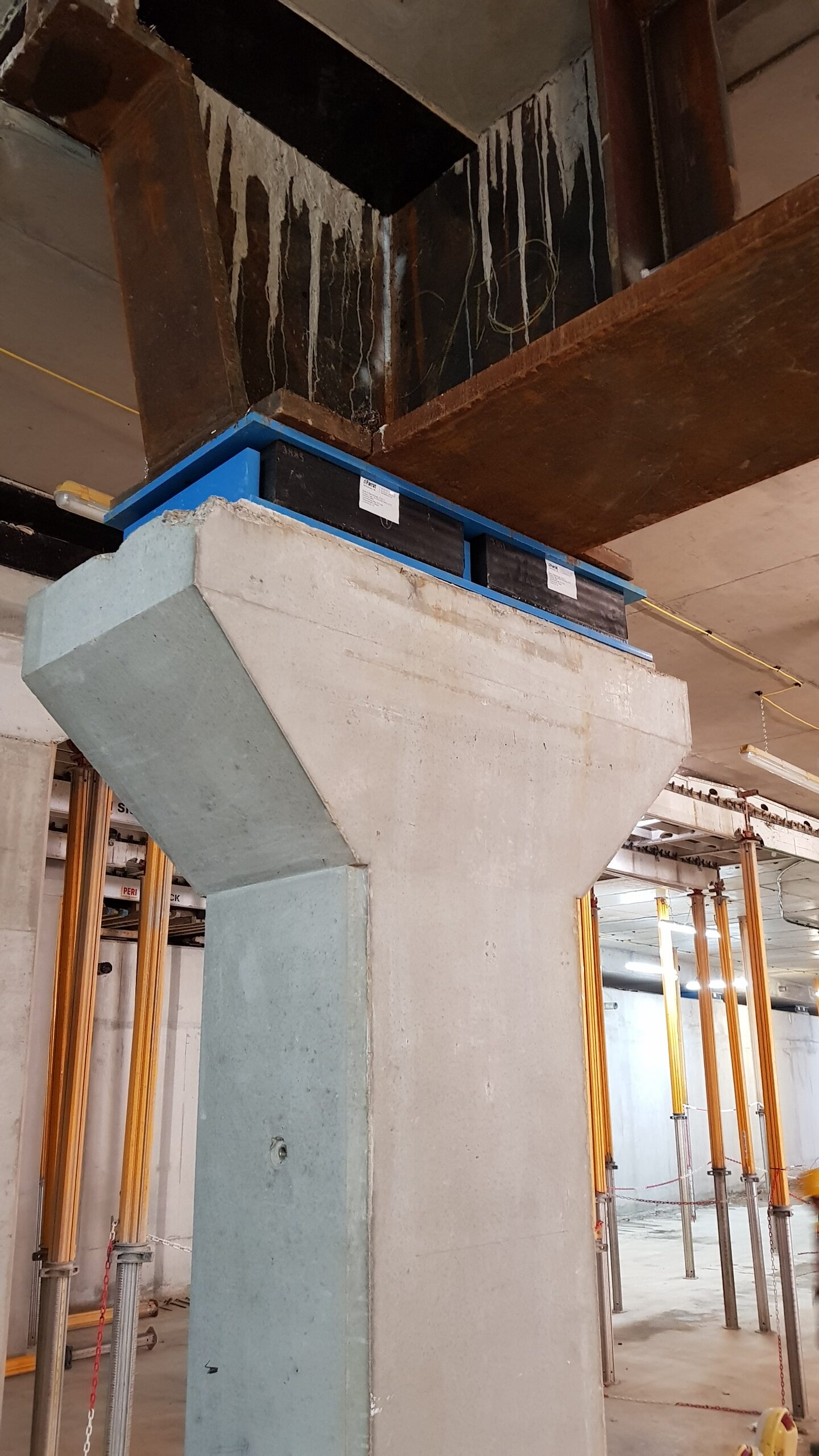
A Farrat 700kN VI Shear Key that can support loads up to 4000kN ULS and resist 700kN ULS of shear force. This is a neat solution as the capacity is much higher than what could be achieved with concrete upstand shear keys and the pre-assembled unit can be craned into position, levelled and grouted in place for quick, easy and safe installation.
For this project, since there were a number of different combinations of vertical loads, shear loads and wall widths we developed a number of variants to this original 700kN version which we now use on other projects.

A photo from early in the construction phase that neatly shows how the whole structure above is supported by Farrat’s LNR Bearings and VI Shear Keys.
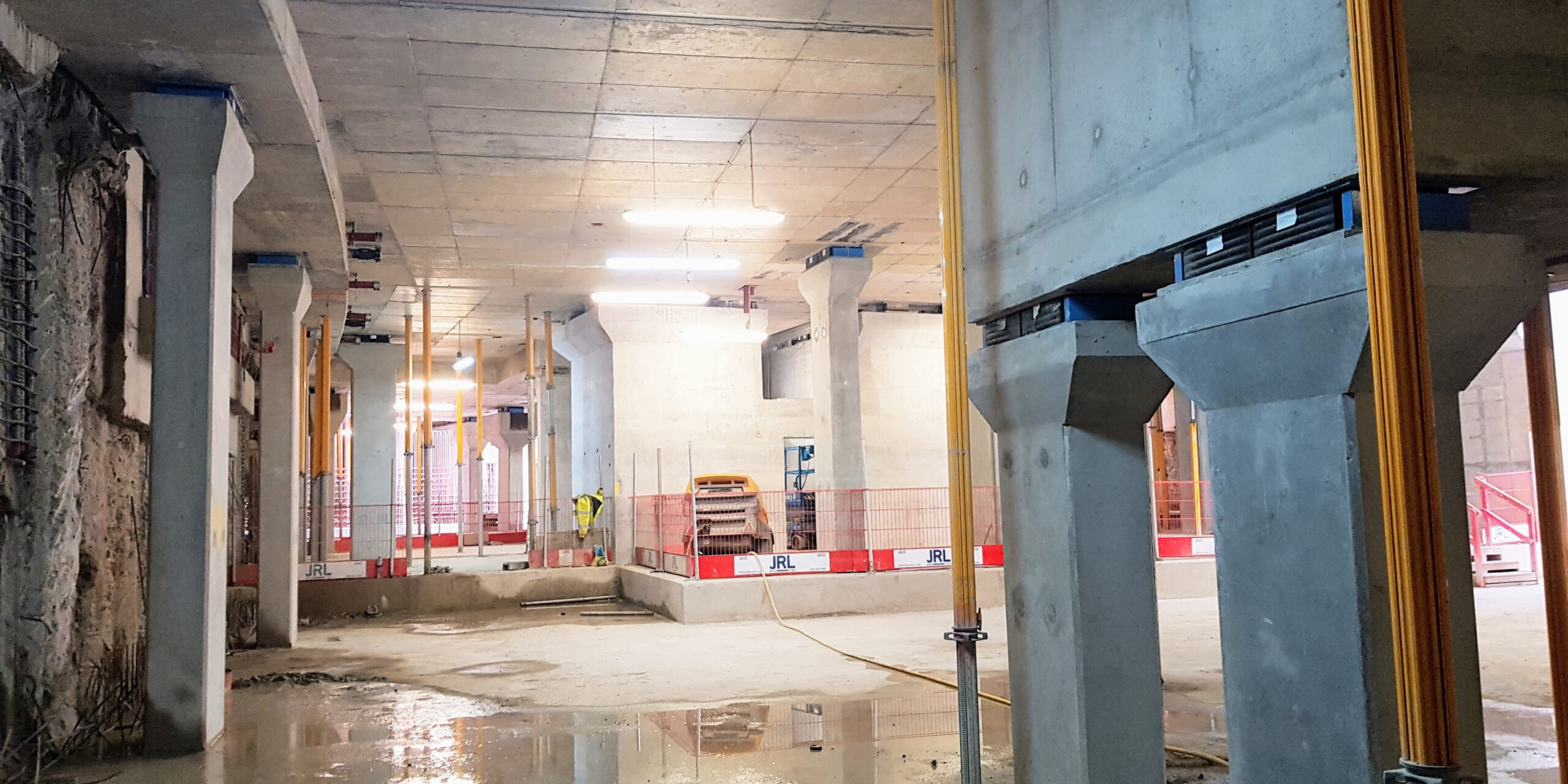
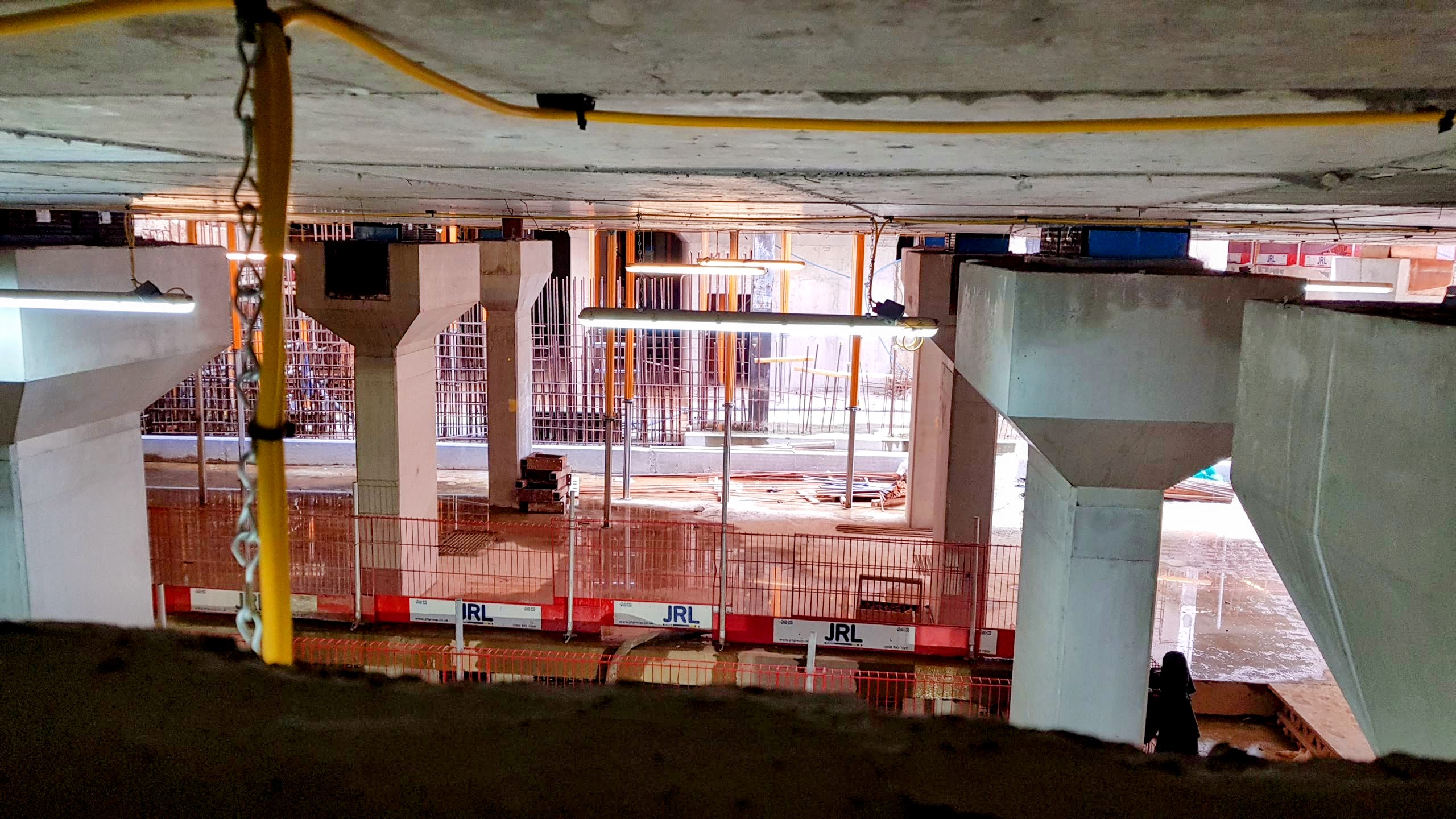
Columns
With such a large building there were a lot of columns. Since in most areas it was only a single level of basement the columns could be designed as key elements with effective length of x2. This simplified the acoustic design as it meant the column bearings only required fail-safes, no lateral restraints or vertical ties.

The keen eye will spot that in a number of columns heads are significantly larger than the bearing. This is because the columns were pre-cast and they were ordered before we had finished the design iteration process. Whilst clearly efficient in terms of manufacturing it is wasteful and goes against our goals of having buildings designed with as little material as practicably possible.
View through a core wall showing LNR Bearings on top of pre-cast columns

Representative photo showing the structure that the Farrat LNR Bearings are supporting
Basement columns in one of the few areas where there was an additional floor level
Some central parts of the structure used a steel beams to enable a larger column grid.

This was one of the few projects where a bearing replacement strategy (in case of Fire) was incorporated from the outset into the structure. The photo shows steel beams set into the ground floor slab above the bearings that would be used to jack the structure up in the event that the bearings are damaged.

Wider angle photo showing columns and cores and the two columns in the foreground have the steel replacement strategy beams set into the acoustically isolated slab.

The mews buildings were designed as a steel structure, part of which had to span and cantilever over the roots of an ancient tree that was in the middle of the site. This steel structure was isolated at its base (ground floor) using the same LNR Bearings and VI Shear Keys as the rest of the RC frame.

Farrat 700kN VI Shear Key supporting and laterally restraining the mews steel structure

The steel structure during erection. Photo also shows the proximity of the neighbouring properties as even though this was a large development it was a very tight site with construction activity happening in all areas at the same time.
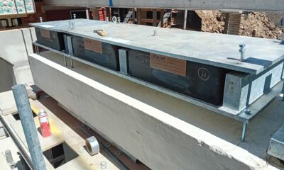
Acoustic Floating Floors

Since the basement was not part of the building vibration isolation system, the parts of the basement that were to be inhabited required acoustic box-in-box systems. Farrat provided an adapted CineFLOOR PRO system with larger air gap, mineral wool and cement particle board formwork (in case of water ingress/leaks) all of which was installed by Farrat Installation Services.
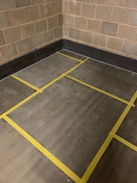
The dry system installed ready to receive the damp proof membrane (dpm) and then concrete.
Midgard provided the following feedback in a referral letter:
“With excellent project management and site supervision, delivered the project on time and on budget. Throughout the construction phase, I witnessed complete co-operation between Midgard, Farrat and our other sub-contractors. I can confidently recommend Farrat for works of this nature and look forward to working with them again.”
“With excellent project management and site supervision, delivered the project on time and on budget. Throughout the construction phase, I witnessed complete co-operation between Midgard, Farrat and our other sub-contractors. I can confidently recommend Farrat for works of this nature and look forward to working with them again.”

This photo, taken just before the concrete was poured (by JRL/Midgard under Farrat’s supervision), shows the whole system with the floating floor below and at high level the ceiling slab is the isolated ground floor slab of the building above. By this point most of the bearings have been hidden by the fire protection.
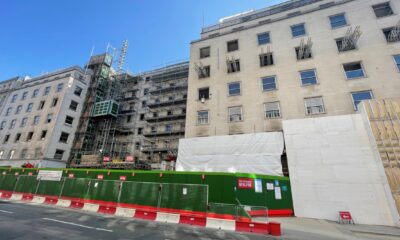
Retained Façade & adjoining buildings

This photo taken back in 2016 shows the section of retained façade in zone 4 and the two existing residential buildings that would eventually become part of the overall development. We developed details for both cases that would carry the relevant multi-directional forces, allow the isolated structure to move freely and not be restricted by these non-isolated structures and ensure no structure-borne noise and vibration could pass across into the new building.

Here we see the new structure and the retained façade behind it with the acoustic brackets running along the slab edge. Their purpose was to provide the stability for the retained façade (which was rigidly supported at its base) at each floor level, to the transmit the horizontal wind loading forces (push and pull) into the floor slabs of the new structure to be resisted by the cores and ensure that the movement of the isolated structure would not lead to cracking in the façade.
Slip membrane for heritage façade
One feature that we supported the project with (as a favour) was to provide a slide bearing/ slip membrane to sit underneath the new heritage façade and prevent it from cracking either from movement in the foundations and thermal expansion and contraction of the façade itself. The vertical load was ~100 kN/m

The photo shows the slip membrane as the black strip running up the middle of the photo sitting on top of a brick course upstand onto which the façade would be constructed.
Entrance bridges

Finally, the project is getting to the end with the last parts being to re-construct the entrance bridges under the colonnade where the inner part is tied to the isolated building and the outer part is resting on the non-isolated pavement.

Here we see the detail of what was constructed with Farrat providing the material to vertically support the columns and bushes to acoustically isolate the shear studs.
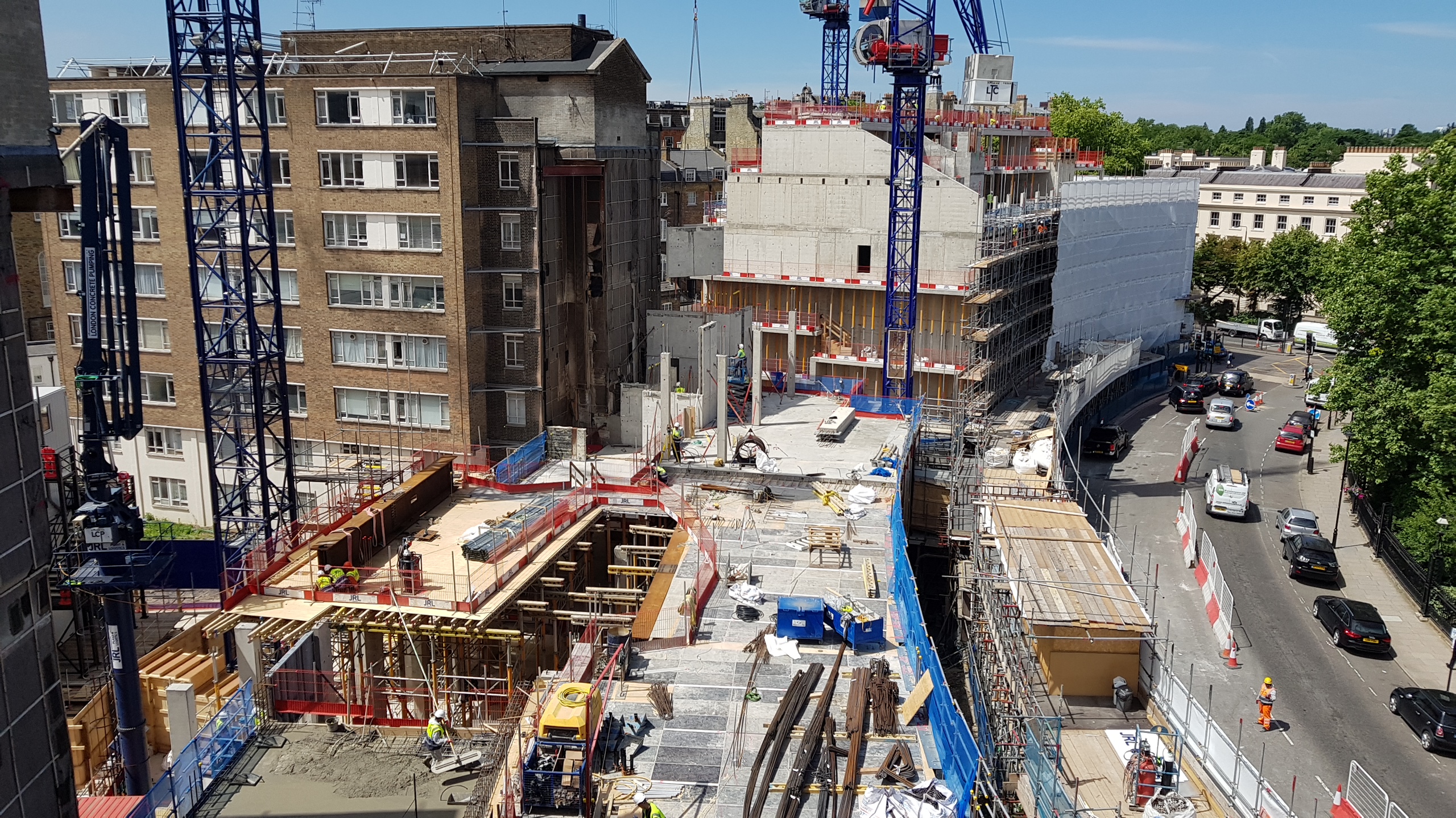
This photo, final taken in June 2018, nicely emphasises the scale and complexity of this project and the intensity of activity to build it. Farrat were proud to have played a part in this interesting, challenging and ultimately successful project.
I am hugely proud of this project spanning 5 years from 2014 to 2019. It pushed us in terms of engineering as well as production to manufacture the volume of products required in a short amount of time but from that we have come out stronger, with new knowledge, enhanced capabilities and experience all of which have brought value to many subsequent projects. I would like to thank all parties involved as that team spirit in design and construction played a big part in the success of the project.
Related Projects
Hotels Ritz Carlton: Wuhan
Farrat provided an optimal floating floor solution to luxury hotel the Ritz Carlton in Wuhan, China.
Challenge our engineers
Contact us now for an initial consultation.