Architects

Architects & Specifiers Portal

Information for designers to aid with the specification of Farrat Structural Thermal Breaks.

Call our Technical Team: 0161 924 1600

Request a Quotation: [email protected]

Farrat offer the market’s only range of thermal breaks that are certified and approved for structural use.


Minimising thermal bridges to the highest industry standards.

Material PropertiesFarrat TBFFarrat TBKFarrat TBL
Compressive Strength, fck (N/mm², MPa)35531289
Elastic Modulus (N/mm², MPa)532651782586
Thermal Conductivity (W/m-k)0.20.1870.292
Thicknesses (5 mm increments)5 to 255 to 255 to 25
Thickness Tolerances (mm)-0 to +0.5-0 to + 0.3-0 to +0.25 (5 MM)
-0.2 to +1.5 (10 MM)
-0.3 to +2.5 (15, 20, 25 MM)
CertificationA2 Fire Rated & BBABBABBA
TBF Datasheet TBK Datasheet TBL Datasheet
TBF NBS Spec TBK NBS Spec TBL NBS Spec

Architects and specifiers are responsible for  addressing some of the biggest challenges facing the world, both now and in the future.  

Meeting these challenges head-on can only happen if you keep up with, create and implement the latest developments in technology and ideas.  

Click to watch our introductory on-demand CPD module, to learn more about ‘Thermal Bridging and Structural Thermal Breaks’.

Or to find out more about how Farrat approaches CPD and keeping your knowledge and skills up to date, by jumping over to our Knowledge Hub.

Key Design Features

Designed to Improve Building Performance and Minimise Energy Loss

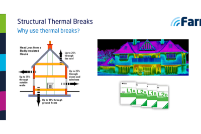
Minimising energy use in buildings has become increasingly important in the drive for sustainability and energy efficiency. Failing to consider the thermal insulation of a structural connection during design, will result in a serious thermal bridge being left untreated later down the line.

Thermal bridges on cantilevered parts of a building are frequently the cause of increased heat loss, damp walls and mould formation.

Farrat Structural Thermal Breaks are used to thermally separate connections and prevent thermal bridges from forming.

Provided as Plates that Work as High-Performance Thermal Insulators

  • Can be used anywhere a penetration or transition exists in the building envelope.
  • Will help to achieve even the most stringent regulatory & energy performance standards.
  • Suitable to mitigate against planar, linear and point load thermal bridging.
  • Eliminates the risk of mould, condensation and corrosion.

Simple to Integrate

Farrat Structural Thermal Breaks are both structurally and thermally optimised. Meaning that they will minimise thermal bridges between components whilst transferring high loads and absorbing any bending moments and shear forces.

There is no need to alter or create elaborate construction details to integrate the thermal break plates into your design.

Farrat TBK, TBL and TBF materials offer full flexibility and can be used in common connection details for cantilever and supported steel balconies, parapets, balustrades, facades, columns, and beyond.

Quick to Specify

NBS Plus authored specifications are available for each material to download above.

Specifications can also be imported directly from within NBS Building and NBS Create, straight into your specification pack.

Clause References:


All Farrat Structural Thermal Breaks can be custom manufactured into various shapes, dimensions, thicknesses and number of/size of hole configurations.

Standard Connection Details

Farrat Structural Thermal Breaks have been optimised to suit common building connections, offering architects full flexibility & freedom of design.

Balconies
External features to internal connections

Façades
Rain screen cladding and façade system connections

Column Base Plates
Structural foundations & column connections

Steel & Masonry (Linear)
Junctions between masonry walls and supporting steelwork

Balustrades (Point)
Point structural connections through insulated roofs & balustrading

CPD Training

Click Here to Book


CPD UK Accredited Seminar

This CPD accredited seminar explains what structural thermal breaks are; why they should be installed and where and how to specify the thermal breaks according to their application.

Technical Enquiries

    ISO-9001 Standard
    ISO-14001 Standard
    Farrat BBA Certification
    Farrat are NHBC Approved
    BRE Logo
    Farrat are a SCI Member

    Case Studies

    Changing Legislation in response to climate change and energy saving has meant that Farrat now supply Structural Thermal Break Plates for the UK and overseas market. 

    Constantly driven by engineering excellence, we continue to lead the way in the development of the Structural Thermal Break Plate market with the following Certifications and membership:

    Farrat BBA Certification
    Farrat are NHBC Approved
    BRE Logo
    NBS Plus Logo
    ISO-9001 Standard
    ISO-14001 Standard
    Farrat are a SCI Member

    Farrat Structural Thermal Breaks have British Board of Agrèment Certification [BBA] audit manufacturing quality plan.

    Farrat Structural Thermal Breaks meet the NHBC’s Technical Requirements. This is referenced in the BBA Certification.

    Farrat is a member of BRE’s Certified Thermal Details and Products Scheme.

    Farrat Structural Thermal Breaks can be found on NBS Plus and NBS National BIM Toolkit and Library.

    Farrat operates under an ISO 9001:2015 Quality Assurance System. This also incorporates BBA’s Product Quality Plan.

    Farrat operates under an ISO 14001:2015 Environmental Management System.

    Farrat is a member of The Steel Construction Institute [SCI].

    bbaFarrat Structural Thermal Breaks are manufactured from high performance materials. We only use materials specifically developed for use within the building envelope and have British Board of Agrement Certification [BBA] to ensure that designers and clients have confidence in the product which is used in structural connections. Every order is accompanied with a Certificate of Conformance. We offer two grades, Farrat TBK and Farrat TBL.

    Material Properties:

    Farrat TBK Farrat TBL
    Product Certification

    Characteristic Compressive Strength, fck (N/mm² , MPa)

    BBA

    312

    BBA

    89

    Design Value for Compressive Strength, fcd (N/mm² , MPa) 250 70
    Elastic Modulus (N/mm² , MPa) 4100 2586
    Density (Kg/m³) 1465 1137
    Water Absorption (%) 0.14 0.48
    Thermal Conductivity (W/m-k) 0.187 0.292
    Colour Amber Black
    Standard Thicknesses available (mm) + 5, 10 ,15 ,20 & 25 5, 10 ,15 ,20 & 25
    Thickness Tolerances (mm) ++ 0 to +0.3 0 to + 0.25 (TBL5)

    +0.2 to +1.5 (TBL10)

    +0.3 to +2.5 (15, 20 & 25)

    Maximum sheet size (mm) 2400 x 1200 2500 x 1250
    + Multiple plates can be provided for applications where thicknesses greater than 25mm are required. Both materials can be supplied in non-standard thicknesses (please contact Farrat for further details).
    ++ Farrat TBL can be supplied to tighter tolerances (please contact Farrat for further details).

    For further details, please refer to our Structural Thermal Breaks brochure.

    bre-logo-largeThermal Design

    There are few standard construction details between projects therefore detailing of the building envelope and penetrations can vary significantly. As a result, the calculation of thermal performance and compliance can be complex.

    There are two aspects to the thermal performance of the building envelope; heat loss and condensation risk. Both issues are covered by Building Regulations and guidance on meeting them is provided in various Approved Documents (England and Wales), Technical Handbooks (Scotland) or Technical Booklets (Northern Ireland). These documents currently require heat loss and condensation risk to be assessed in accordance with the same British Standards, European Standards and BRE Publications. Unlike proprietary mechanical thermal break systems, the plate type thermal break is very simple to incorporate into most details. This flexibility means that it can be used for a wider variety of applications and is not restricted by the modular nature or the space required for proprietary mechanical systems. This flexibility also provides the Designer with greater freedom to develop a bespoke solution.

    Thermal Design Considerations:

    How thick does the thermal break need to be?

    Ideally the construction detail should be thermally modelled. This requires not only the members and connections, but the entire fabric of the envelope local to the connection to be included in the model. This applies to both mechanical and plate type thermal breaks. This issue is often forgotten or considered late in the construction process and due to the cost and time implications, modelling is often not undertaken. However, modelling should be considered where:

    • the environmental conditions pose a greater risk (e.g. swimming pools)
    • the detailing of the planar elements local to the connection are considered to have an inferior thermal performance to that of the main building envelope
    • there is significant repetition of the same detail (e.g. balconies).

    If thermal modelling is not undertaken, the following should be considered:

    • The thermal break should be located within the insulated zone of the building envelope.
    • Selection of the thickest thermal break (up to 25mm) considering cost, thermal performance and structural requirements (limitations).
    • Minimisation of the cross sectional area/ mass of the steelwork penetrating the building envelope where possible.
    • The performance of the connection detail against the BRE’s Certified Farrat details – information provided below.

    Stainless steel bolts are sometimes specified for durability reasons. Isolation using normal methods may need to be considered because of bi-metallic action and corrosion. Isolation using thermal washers and thermal bushes will provide minimal additional thermal performance.

    Point thermal bridge

    The quantity which describes the heat loss associated with a single penetration is a point thermal bridge(χ-value, W/K). This is a property of the thermal bridge and is the rate of heat flow per penetration that is not accounted for in the U-values of the plane building elements containing the point thermal bridge.

    Linear thermal bridge

    The quantity which describes the heat loss associated with a thermal bridge is its linear thermal transmittance (Ψ-value, W/m·K). This is a property of a thermal bridge and is the rate of heat flow per degree per unit length of the bridge that is not accounted for in the U values of the plane building elements containing the linear thermal bridge.

    Condensation risk

    The Specifier will usually identify indoor and outdoor temperatures and relative humidity conditions under which condensation must not occur. Guidance on suitable conditions is given in BS 5250 Code of Practice for the Control of Condensation in Buildings. From these conditions it is possible to determine the allowable minimum temperature on the construction detail below which there would be a risk of condensation. Finite Element Analysis and similar analysis methods allow the temperature distribution to be predicted. 

    If outside of the UK, then refer to local standards to determine modelling design parameters.

    Temperature factor

    The temperature factor (f) is used to assess the risk of surface condensation or mould growth and is calculated under steady state conditions. To avoid problems of surface condensation or mould growth, the fRsi should not be less than a critical temperature factor (fCRsi).   A range of appropriate critical temperature factors are identified in BRE Information Paper IP 1/06 and listed below:

    Building type Critical Temperature Factor (fCRsi)
    storage buildings 0.30
    office, retail premises 0.50
    dwellings, residential buildings, schools 0.75
    sports halls, kitchens, canteens 0.80
    swimming pools, laundries, breweries

    .

    BRE Certified Thermal Products Scheme

    Farrat is a member of BRE’s Certified Thermal Details and Product Scheme. The scheme database includes for both BRE Certified Thermal Details and Products and Government Accredited Details, and this provides a freely accessible and independently assessed and certified resource for users. The third-party BRE Global certification can distinguish products and services from their competitors, and give customers confidence about the thermal performance of the products.  

    The database has been developed to enable details to be linked directly into SAP 2016 and is also featured within the BRE Home Quality Mark standard. You can view a full list of industry members here: BRE Scheme Members.
    A number of typical connection details have been analysed under the Scheme to assist Designers when specific modelling of their details is not undertaken. All details assessed (Ref 600063 to 600068) had a temperature factor above 0.80, meaning mitigation against risk of surface condensation. This includes:
    • storage buildings
    • offices
    • retail premises
    • dwellings
    • residential buildings
    • schools and sports halls
    • kitchens and canteens
    The ‘small beam’ steel to steel connection (Ref 600063) had a critical temperature factor above 0.90, meaning that in addition to the above there is also no risk of surface condensation for:
    • swimming pools
    • laundries
    • breweries

    Thermal Modelling Specialists

    Graeme A. Hannah (MEng PIEMA)

    Programme Director, Centre for Resilience

    BRE Certified Thermal Details and Products Scheme

    T: +44 (0) 1355 576 225  E: [email protected]


    Annalisa Simonella  (MSc [Eng], LEED Green Associate, WELL AP)

    Director, an-imo Consulting

    T: +44 (0) 141 258 6768  E: [email protected]


    Dr. Richard Harris

    Partner, Consultancy Department

    T: +44 (0)20 7565 7066  E: [email protected]

    Steel to Steel - Thermal bridging
    • Thermal bridge in a connection without a Farrat Structural Thermal Break. The temperature of the steel is on the hot side of the outer-wall system (9.8°C) and heat loss (χ value) is 1,31W / K.
    Steel to Steel - reduced Thermal bridging due to application of Farrat thermal break.
    • Distribution of temperature with Farrat Structural Thermal Break plate  (TBK). The temperature on the hot side of the facade system has been improved to 16.5°C and the heat loss is limited to 0.35 W/K = 73% less heat loss.


    logo_sci_memberStructural Design

    Under the SCI Assessed Product Scheme the technical data and structural design methodology for Farrat Structural Thermal Breaks has been independently verified by the SCI. The design considerations are set out in the Farrat Structural Thermal Breaks Connections Guide. Unlike proprietary mechanical thermal break systems, the plate type thermal break is very simple to incorporate into most details. This flexibility means that it can be used for a wider variety of applications and is not restricted by the modular nature or the space required for proprietary mechanical systems. This flexibility also provides the designer with greater freedom to develop a bespoke solution.  

    Structural Design Summary (steel connections)

    Connections that include thermal break plates should be designed in accordance with the relevant design standards (e.g. BS EN 1993-1-8) or industry guidance (e.g. SCI publications). The following additional checks should also be undertaken, check that:

    • the thermal break plate can resist the applied compression forces.
    • any additional rotation due to the compression of the thermal break plate (including allowance for long term creep) is acceptable.
    • the shear resistance of the bolts is acceptable given that there may be a reduction in resistance due to:
      • PACKS –  Clause 6.3.2.2 of BS 5950-1 or clause 3.6.1(12) of BS EN 1993-1-8
      • LARGE GRIP LENGTHS – Clause 6.3.2.3 of BS 5950-1 or BS EN 1993-1-8


    Structural Design Generally

    For connections involving concrete and masonry, the material principles detailed above should be considered in conjunction with the relevant Eurocodes. All connections involving proprietary fixing systems (non-standard) may require consultation with the product supplier.

    Structural Design Considerations:

    Fire

    Thermal break plates are contained within the protective envelope of the building and in general Building Regulations do not require them to be fire protected or have a fire performance rating. Where the connection containing the thermal break requires fire protection then the following options can be considered:

    Board Protection A number of proprietary fire protection board systems are available on the market.
    Sprayed Fire protection A number of proprietary sprayed fire protection systems are available on the market. The manufacturer should be consulted regarding the compatibility between the system and the thermal break materials. Alternatively consideration can be given to recessing the thermal break and providing a continuous fire protection strip (Nullifire etc.)

    Contact Farrat if the connection requires a fire rating.

    Fire Engineering
    • Consideration of complete loss of the thermal break plate
    • Introduction of “fail safes” – refer to section on robustness
    • Computer modelling or physical testing of the connection/ panel

    Robustness

    The majority of thermal break connections are related to secondary elements only. The Structural Engineer will consider robustness during the design process and will refer to local codes and standards. Where a structural thermal break is located within a key critical element this may need further analysis leading to either consideration of the complete loss of the thermal break or inclusion, for example, of a physical “fail safe”. The detailing of this can often be undertaken whilst maintaining the thermal performance of the connection.

    Handling on site

    Thermal breaks are normally procured by the steel fabricator as part of the steel frame package on a project. The delivery from Farrat is normally co-ordinated with the steel work contractor erection schedule. They are delivered to site with each one labelled with a unique reference linked to the steel work contractors drawings. For identification purposes Farrat TBK and TBL are different in colour. If it is essential to the project that both materials are used on the same project, Farrat normally advise that the connection arrangement (e.g. bolt positions) is unique to ensure that no errors are made during installation. This is in addition to Farrat’s normal labeling protocol.

    The general handling requirements for thermal breaks should be in line with other component accessories expected to be handled with the primary steel work. This is covered in the NSSS: Section 8 Workmanship – Erection. The NSSS also sets out the requirements of the Quality Management System expected to be adopted by all competent steelwork contractors working on UK construction projects.

    For concrete frames, reference should be made to the National Structural Concrete Specification for Building Construction.

    Farrat Thermal Break - 4 Bolt Connection
    • Structural Thermal Break Plate (TBK) with 4-hole connection, steel-to-steel.

    Typical Applications:

    Farrat Structural Thermal Breaks can be used in a wide variety of applications where there is a structural requirement of the thermal insulation:

    • Steel to steel
    • Steel to concrete / masonry
    • Steel to timber
    • Concrete to concrete
    Farrat Thermal Break - Steel to Steel Connection
    Farrat Thermal Break - Steel to Steel Connection
    Farrat Bearings in Application

    Building Elements:

    • Facade system connections to the primary frame
    • Brise Solei and Canopies
    • Roof plant room columns
    • Balustrading
    • Connections of external to internal primary building elements
    • Isolation of sub-structure & basement structure elements
    • External staircases or external balconies
    • Man-safe systems
    • BMU Systems
    • Connections to existing structures
    • External Signage
    cantilever walkway with glass balustrade
    Structural Thermal Breaks used on stainless steel balcony
    Structural Thermal Breaks used between concrete columns

    Farrat’s market leading Structural Thermal Break Plates & Pads (FSTB) are high performance thermal insulators, used between horizontal and vertical connections of internal and external elements to prevent thermal/cold bridging.

    Key Features

    • Mechanical properties of the materials aligned for building applications
    • High or very high strength options
    • Low thermal conductivity (k)
    • Ability to be manufactured in 2D or 3D (i.e. recess, chamfer, etc.)
    • Variety of thicknesses available. Special thickness/tolerances available to specifiers

    Key Benefits

    • British Board of Agrément Certification [BBA]
    • A simple and effective solution to meeting Building Regulations
    • Not a proprietary modular mechanical system – so offers the designer scope to develop bespoke connection detailing
    • Supported by technically qualified staff
    • Supported by external organisations including BBA, NHBC, NBS and BRE
    • Manufactured under Farrat’s ISO9001:2015 & ISO14001:2015 Systems
    • Manufactured under BBA’s Quality Plan which is externally audited
    • Manufacturing capacity allowing us to meet your lead time

    Construction drawings Should show a fully detailed connection or one communicating the design intent with a supporting specification (NBS or similar). The Architect Is normally responsible for ensuring that the connection meets the requirements of the Building Regulations Part L (SAP). Design Output – Thermal performance/ Thickness (Farrat TBK or Farrat TBL). The Structural Engineer Is normally responsible for designing the connection or providing a performance specification for the connection. Design Output – Strength (Farrat TBK or Farrat TBL)


    nbs-plus-stamp_rgb

    Sample Specification for project using Farrat TBK – National Building Specification (NBS) NBS Clause: G10/ 350 Structural Thermal Break Connection Plate

    • Manufacturer: Farrat Isolevel Ltd, Balmoral Road, Altrincham, Cheshire, WA15 8HJ, Tel: +44 (0)161 924 1600, Fax: +44 (0)161 924 1616 farrat.com
    • Product Reference: Farrat TBK
    • Thickness: 25 mm
    • Plate Size: As Drawing number – or to be determined by the connection designer
    • Hole Size & Positions: As Drawing number – or to be determined by the connection designer
    • Certification – British Board of Agrément (BBA)

     Please be aware there are cheaper materials on the market that the supply chain may provide as an alternative, but in our view not of equal performance or certificated for use in building applications (structural).

    To enable us to provide a quotation, we will require the following information for each plate:

    • Material – Farrat TBK or Farrat TBL
    • Plate Dimensions
    • Plate Thickness
    • Size and Number of Holes
    • Quantity
    • Any Special Requirements
    • Delivery Location

      To accept orders, our manufacturing facility will require a fully dimensioned drawing with each plate type having a unique customer reference (drawing number).

    Farrat FTB enquiries-diagram

    We aim to start manufacturing within 3 working days of receiving the order and you will be advised of a despatch date. We can very often start manufacturing sooner, and can work with you on very large orders to meet your programme and requirements.

    • Each plate has a label attached [Farrat/BBA]
    • Each order will be accompanied by a Certificate of Conformance under our British Board of Agrement Certification.