Following our webinar with The Institute of Structural Engineers on how to achieve high-performance specifications for structure-borne noise and thermal bridging with minimum mass and materials, we’d like to share the answers to the questions asked during the event.
If you would like to ask our team any other questions, you can email us or call us at +44 161 924 1600.
What was the acoustic specification from Level and how was this translated into the acoustic performance of the bearings?
The acoustic specification was quite complex. So there’s a specification for the through-wall acoustic performance, so that’s through both leaves of the system. That focused on the lowest frequency so there was an insertion loss for 63hz and 125hz, and these were high, so more than 60db of sound reduction.
When you unpacked that specification, then there is also different components, so there was an acoustic requirement for the sealing between the panels and also a dynamic requirement.
And then the last part of it was to control the structure-borne transmission, which is where the bearings come in. For the whole package to work to achieve more than 60db, the insertion loss of the bearing had to be 33db at 50hz, and that’s right on the limit of what is practical.
With the amount of testing and retesting we needed to do, it’s clear we couldn’t have got that level of precision with springs.
Where did the design responsibility for the connections back to the steelwork lie? Did Farrat design everything up to the supporting steelwork and then William Hare’s everything after that?
This connection actually contained three areas for responsibility. Concrete side Expanded/Laing O’Rourke // Bearing assembly Farrat // Structural Steelwork William Hare.
The concrete panel and the stub or halfens channel cast into the concrete were the responsibility of Expanded. The bearing assembly, ie all steel pieces in direct contact with the rubber and the rubber bearings themselves were Farrat’s responsibility
The supporting structural steelwork onto which the assemblies connected were William Hare’s responsibility. Further complications arose on the horizontal top corner of panel connections, where a through bar required two additional steel plates to connect to the steelwork – Farrat supplied these as well as accompanying fixings. We found that colour-coded drawings were key to ensuring the project teams were aware of where one responsibility ended and the next began (for example. all orange items are Farrat, all blue are William Hare etc)
Is there any deviation of the acoustic from the acceptable level? If have what is the remedies action taken?
The original intention was to break down the different components – the bearings, the panels, and the sealants – and have an individual benchmark performance for each of those. It quickly became clear that there was so much variation between the individual panels that this would not be successful.
Instead, the acid test is whether the through wall acoustic performance met the requirements, and then we took every panel in turn and looked at the composite effect of the performance of each of the bearings in each of the directions.
There are occasions where, because we were assessing the insertion loss across the spectrum, narrowly we weren’t meeting our ambition for sound insulation, and then we’d have to make the decision on whether that mattered or not. Sometimes it did and then we’d have to go back and redesign. Sometimes it didn’t, and the reason it didn’t is that because of our models, we could assess the significance to the surrounding area of one bearing or panel.
Something to add is that we were able to engineer a much better seal between panels than we were expecting, so that gave us some ‘credits in the bank’. We could then use those ‘credits’ for if a bearing was not performing as well as we would like. My advice to anyone doing a project such as this in the future is to aim to get those ‘credits’ so you have that flexibility.
Was there a modal response design of the shell? And did it impact any parts of the design?
Yes – we had to consider modal performance of the frame and panels simultaneously.
What was the most challenging issue faced at the construction stage? i.e. out of tolerance positioned bearing?
Specific to our assemblies, vertical positional tolerance caused a number of headaches. With most bearings acting in pairs, if one was even 5mm higher than its partner, it would experience higher deflection by trying to take more than its share of the load.
As such all locations had a healthy allowance for localized packing below the assemblies – to ensure both partners were perfectly leveled.
We also found that rotation caused some issues, this was due to tolerance stack-up. For example in some locations both concrete and steel were slightly off perfect 90° angles, but still well within the project tolerances.
However when combined this meant our connection was facing options beyond expectation (for example 3° + 4° gives an actual 7° misalignment between our top and bottom assembly plates, which had the potential to create pinch points in our design. These issues were resolved through the use of location-specific angled packs, to give our assemblies parallel top and base plates.
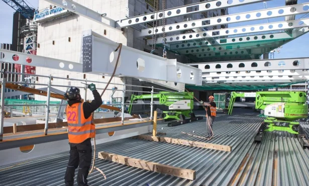
None bearing specific, the Plane 04 face of the theatre faced significant challenges during construction, due to a lack of crane access beyond the overhang formed by the steel frame above.
In the end, a custom-built frame was produced to allow the concrete panels to be maneuvered into place on the theatre while hanging from a crane above, a significant site challenge overcome by brilliant work from William Hare
.
Do you have any thermal information available on the Falcon units, ie psi-values, or a calculated thermal conductivity equivalence that can be used in a 3D thermal model?
Yes, we have been given detailed drawings specifying dimensions and thermal conductivity, this is crucial for bespoke analysis. When we build the thermal models, using the given information, we can deduce a psi value using standardized assumptions taken from the international standard 10211.
The psi value is between 0.3-0.6 W/mK depending on prescribed conditions and thermophysical properties (which dictate the U-value [W/m2K]). We are running various scenarios, using 3D FEA, to inform the development of the product.
Are there any specific solutions for steel to rubble stone, ends in walls and horizontal wall connections?
It’s most likely there could be a solution, however, we have yet to see never Steel-to-Stone (Rubble). Steel-to-Concrete is common and we are now seeing more Concrete-to-Concrete such as in our Falcon solution. If you have a specific project in mind get in touch with the team at Farrat and we’d be interested to hear more about it.
Challenge our engineers
Challenge our engineers to ensure the efficiency and safety of your projects. Email us or call +44 161 924 1600 to talk to the team.
- More about Acoustic Isolation in Concert Halls and Theatres.
- More about Building Vibration Isolation.
- More about Structural Thermal Breaks.