
Welcome, to the Farrat Knowledge Hub. Register to access our free CPD learning resources, technical data sheets, certifications and technical papers.
Knowledge-Hub
Why invest time in Continuing Professional Development (CPD)?
CPD is an important way of maintaining your technical knowledge and stay at the cutting edge. In a fast-moving industry CPD supports you to work safely, legally and effectively.
All Farrat Continuous Professional Development is certified by The CPD Certification Service, the world’s leading and largest independent CPD accreditation institution.
This accreditation ensures that not only can you be assured that all of Farrat’s CPD is factually correct and of the highest quality, but up to date and relevant to your industry.
![]()
Accreditations & Certifications:


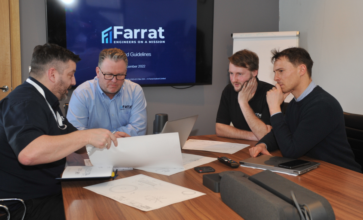
Request a CPD session
To request a bespoke CPD session for your team contact us with your specific training need.
Alternatively you may register for an account and select a module from our extensive library.
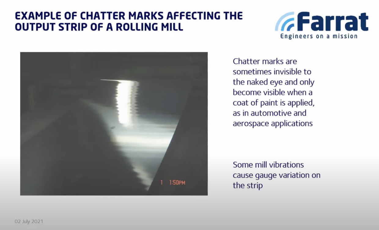
Technical Webinars
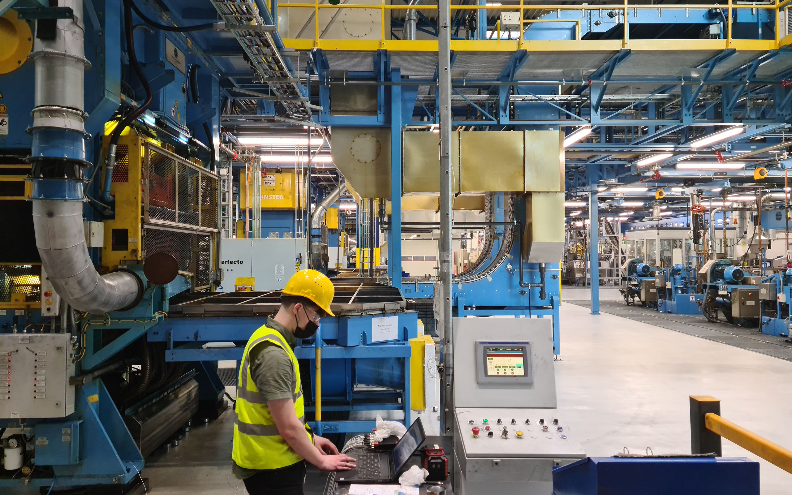
Our technical webinar recordings and presentations provide valuable information on a range of topics.
From vibration control techniques for impact machinery to managing thermal bridging on external connections to acoustic detailing for various building types and applications.
Register to access our library.
What to expect
Once you have registered you will be able to access our extensive library 24/7. We will notify you when anything new is added however you are in total control of what and when you receive information from us.
Benefits for joining the Knowledge Hub:
- Technical Webinars
- On-Demand CPD Library
- Technical Papers
- Download Technical Data Sheets
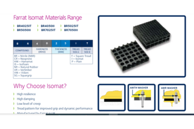
TDS Downloads
CPD Presentations
NBS Source is fully integrated with our Knowledge-Hub so you can specify our products directly.