181 Talgarth Road

London, United Kingdom
Industrie
Bauwesen
Sektor
Urbanes Leben
Gebäudetyp
Hotel
Bauelemente
Betonrahmen, isolierte Erdgeschossplatte

Das Projekt

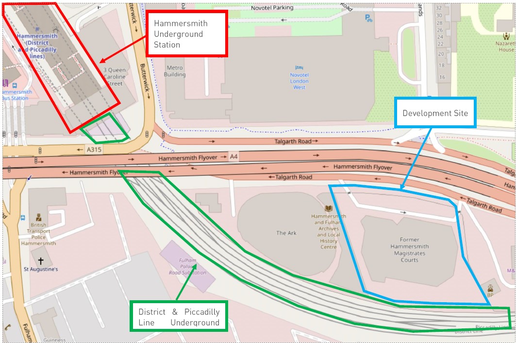
Entwickelt von Herr und entworfen von Rogers Stirk Harbour + Partners Dieses Bauprojekt umfasst Studentenwohnungen und ein Hotel mit 400 Zimmern, das auf dem ehemaligen Gelände des West London Magistrate’s Court errichtet werden soll. Das Projekt war jahrelang immer wieder auf Eis gelegt worden, doch im Dezember 2022 wurde schließlich ernsthaft damit begonnen, als Whitby Wood, mit dem wir in der Vergangenheit bereits eine Reihe von Projekten erfolgreich umgesetzt hatten, wandte sich an uns und bat um Unterstützung bei der Planung des Schwingungsisolierungssystems für das Gebäude. 


Unser Beitrag für das Projekt

Abgesehen von der Qualität und Leistungsfähigkeit des von uns gelieferten Systems ist der entscheidende Mehrwert, den wir Was zählte, war Geschwindigkeit. Wir haben von Anfang an sehr schnell reagiert, Fragen beantwortet und die Entwicklung eines Entwurfs, der auf der Grundlage von Erfahrungen die entscheidenden Aspekte und Einschränkungen des Projekts. Dieses Tempo hielt während der gesamten Detailplanung, Fertigung und den Auftragnehmer während des gesamten Installation. 

Isabel Wykes
Dominika Maciejewska
Projektleiter
Das Projekt 181 Talgarth Road wird mir immer in Erinnerung bleiben, da es mein erstes Projekt als Projektleiter war. Dank meiner dreijährigen Erfahrung als Anwendungsingenieur bei Farrat, der großartigen Unterstützung durch die Hauptingenieurin Adriana Leotta und die gesamte Produktionsabteilung konnte ich die Arbeit an diesem komplexen, aber zügigen Projekt wirklich genießen. Eine meiner Lieblingsaufgaben waren die Inspektionen vor Ort, bei denen ich den Fortschritt der Installation überprüfen und sehen konnte, wie sich unsere Arbeit in der Entwurfs- und Produktionsphase in ein reales Gebäude im Zentrum von London verwandelt.
The site is bounded to the north by Talgarth Road and the eastern approach to the Hammersmith Flyover, and directly to the south by the District (12 trains per hour each way) and Piccadilly (24 trains per hour each way) London Underground Lines as they approach Hammersmith Station to the northwest. The hotel operator’s requirement regarding re-radiated noise from railway trains not visible from the bedroom window when measured at the bedhead shall not exceed 30dB LAF,max. The acoustic consultant RBA Acoustics’ vibration analysis predicted that the typical worst-case levels were up to 48 dB LAF,max meaning the building vibration isolation system need to achieve a reduction of nearly 20 dB LAF,max which from experience from previous projects was highly achievable with a well designed and constructed 8Hz system.
The rest of the development, including the 10-story part of the hotel, was deemed to not require vibration isolation.
On first impression it is perfectly reasonable to assume, as the contractor, HG Construction did, that this is wasteful and overly expensive because the ground floor did not need isolation. However, when viewed holistically, the additional cost to isolate the ground floor using Farrat’s innovative VFT System, would be less than the costs involved in: 1. Restraining each column in case of notional horizontal loads and disproportionate collapse whether isolated at the top or bottom of the column. 2. Allowing differential movement between the isolated columns and non-isolated ground floor slab whilst maintaining fire protection, waterproofing and thermal insulation. 3. Acoustically isolating every interface between the non-isolated ground floor and the isolated first floor slabs including façade, services, internal walls, fixtures and fittings etc. And then policing their construction throughout the project to ensure no bridging has been created.
Once all avenues had been explored it was agreed to proceed with this design. Since it was a multi-building site, the contractor could concentrate on other buildings in the development to allow time to design and manufacture the building vibration isolation system.
Farrat and Whitby Wood worked intensively and collaboratively to incorporate the vibration isolation system into the structure. Starting with identifying the key structural nodes of columns, cores and shear walls and then undertaking the load modelling process to integrate the LNR acoustic bearing spring stiffnesses into the structural load model. Once the LNR bearing design was fixed, the next stage was the lateral restraint design using Farrat’s standard 700kN VI Shear Key to resist all shear loads passing along the core and shear walls.
With the positions and types of each element now designed Farrat’s team created detailed setting out and installation instructions for the LNR Bearings, VI Shear Keys and VFT System in order that the system could be installed by the contractor without the need to a specialist installation team.
Following an accelerated manufacturing programme, materials were delivered to site within 6 weeks of the design being completed. Here we see 700kN VI Shear Keys and LNR Failsafe Assemblies delivered and ready to be installed.
Farrat VFT System delivered to site.
A Farrat 8Hz LNR Failsafe assembly ready to be grouted in place. The unit comes with lifting eyes for easy movement and placement on site and levelling screws in each corner to minimise installation time and avoid fiddly shims. The steel plates above and below the LNR bearing helps spread the load into the concrete reinforcement.
Levelled and grouted LNR assembly with VFT System laid around it onto which the ground floor slab’s thermal insulation is laid.
8Hz VI Shear Key levelled and grouted with VFT System laid around it and the thermal insulation in the background.
General view of the construction methodology.
In the advanced stage of installation with the thermal insulation laid onto which the gas membrane and waterproofing (yellow) is laid ready to receive the ground floor slab.
During installation of the reinforcement for the ground floor slab. In the bottom left of the image you can see the rebar constructed around the shear and tension studs protruding from a 700kN VI Shear Key. This image nicely demonstrates that once the floor slab is cast the entire building is isolated and construction can continue without worrying about follow on trades bridging the building vibration isolation system.
Feedback