181 Talgarth Road

Londra, United Kingdom
Industria
Costruzione
Settore
Vivere urbano
Tipo di edificio
Albergo
Elementi costruttivi
Telaio in cemento armato, piano terra isolato

Il progetto

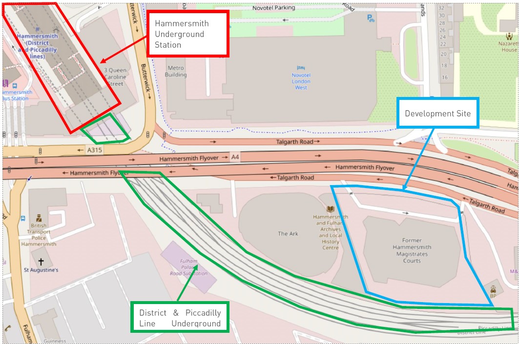
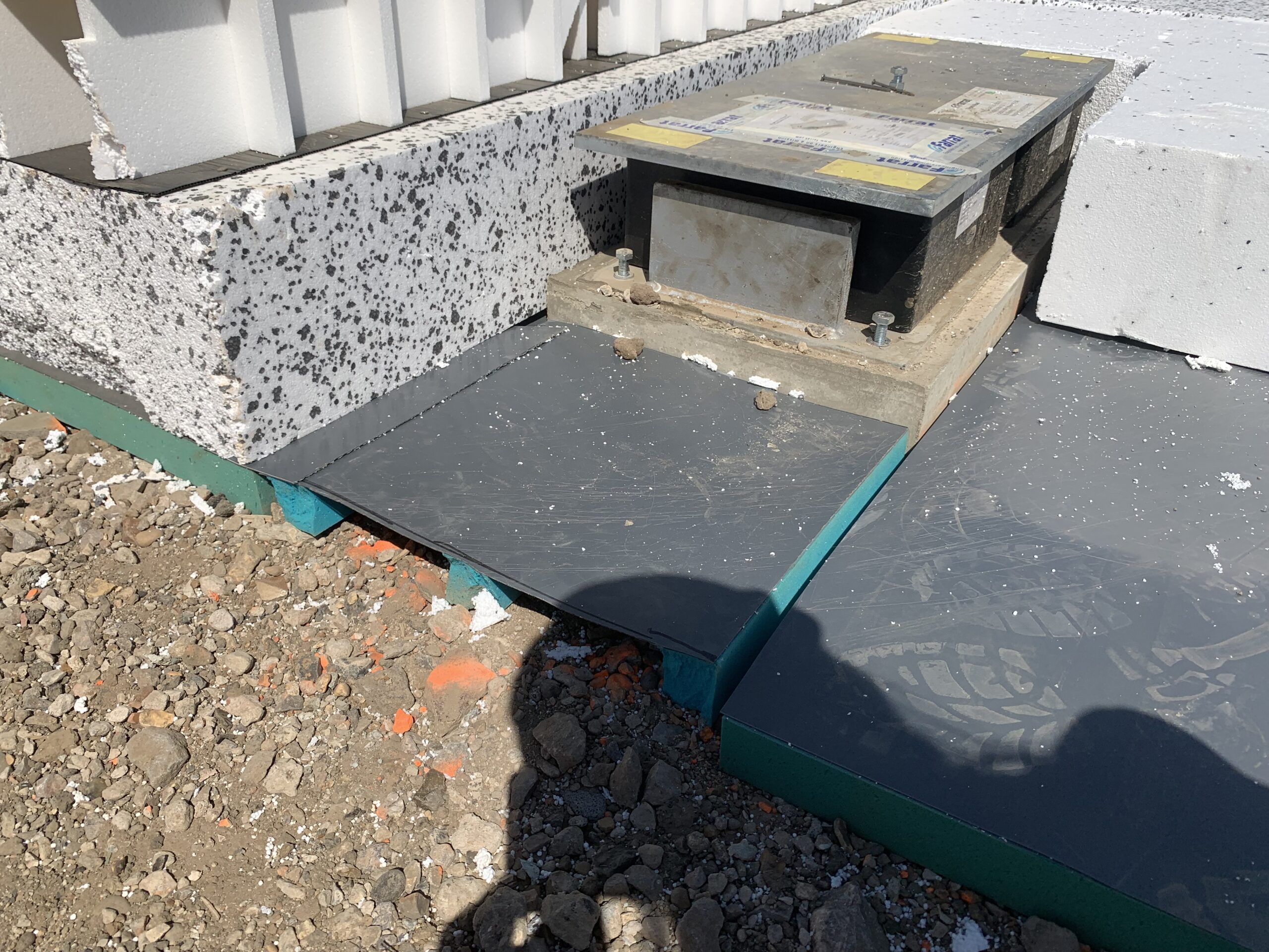
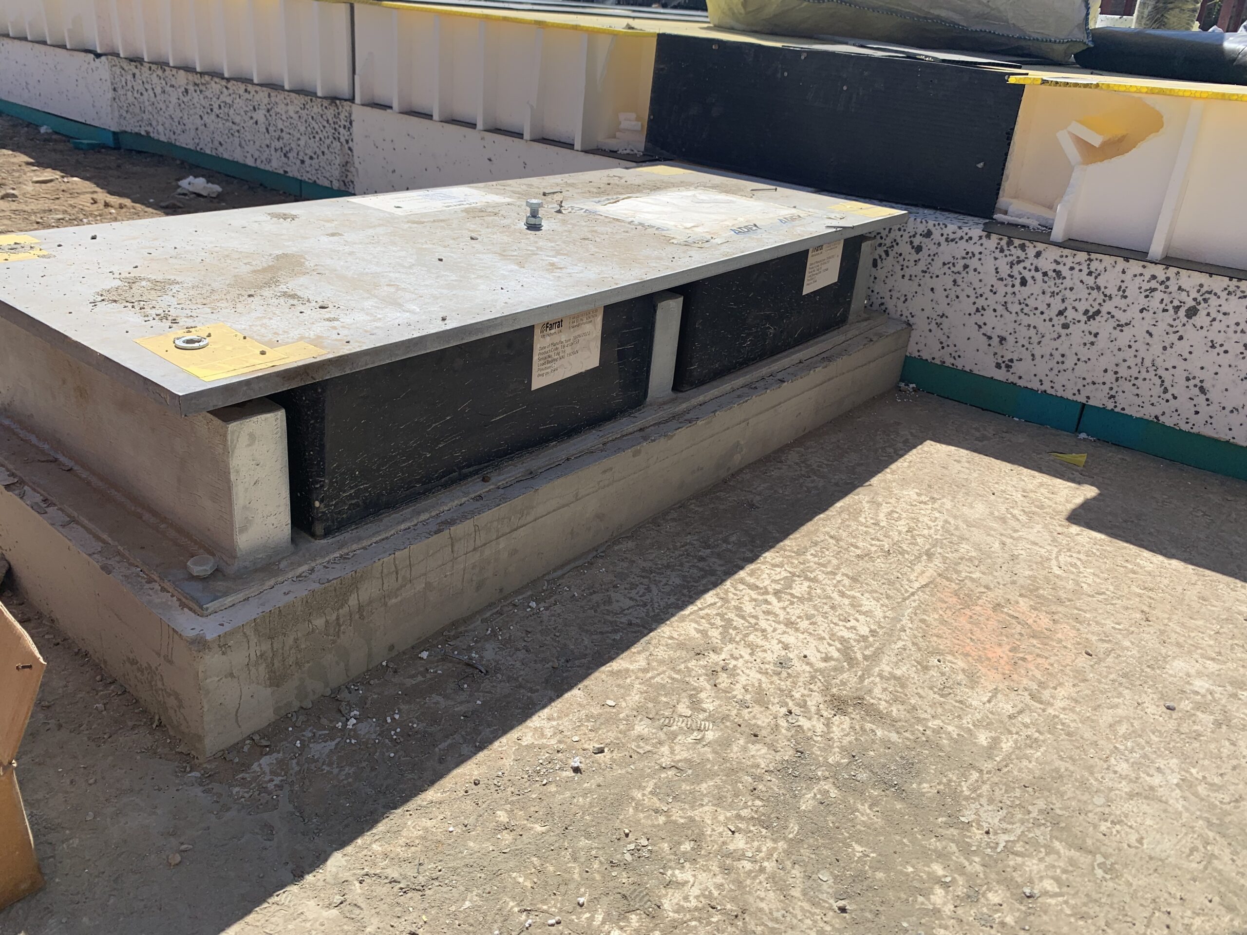
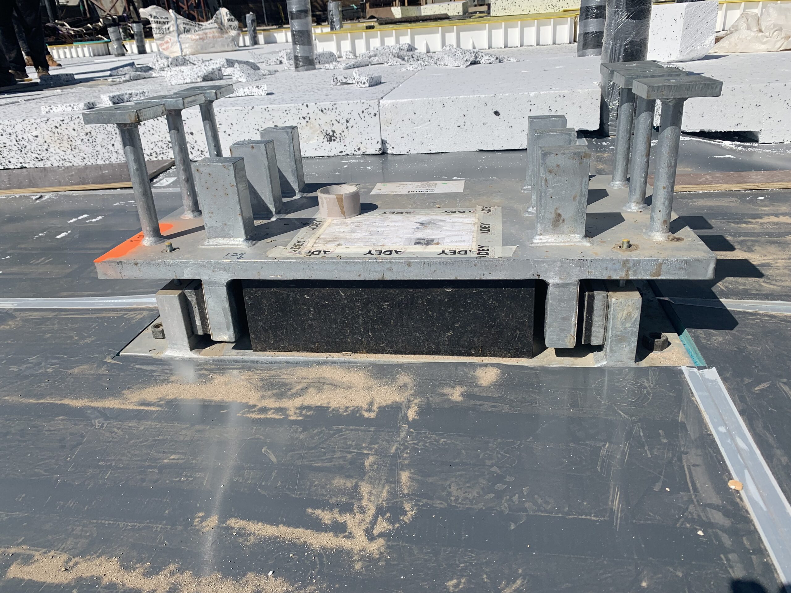
Sviluppato da Dominus e progettato da Rogers Stirk Harbour + Partners Questo complesso è costituito da alloggi per studenti e da un hotel da 400 camere che sorgerà sul sito dell’ex tribunale di West London. Il progetto era rimasto in sospeso per anni, ma alla fine è stato avviato definitivamente nel dicembre 2022 quando Bosco di Whitby, con cui avevamo già realizzato con successo diversi progetti in passato, ci ha contattato chiedendoci assistenza per la progettazione del sistema di isolamento antivibrante dell’edificio. 


Il valore chiave che abbiamo apportato al progetto

Oltre alla qualità e alle prestazioni del sistema che abbiamo fornito, il valore fondamentale che ciò che contava era la velocità. Fin dall’inizio ci siamo dimostrati molto reattivi, rispondendo alle domande e elaborare un progetto che, sulla base dell’esperienza, tenesse conto gli aspetti critici e i vincoli del progetto. Questo ritmo è proseguito per tutta la fase di progettazione dettagliata, produzione e affiancando l’appaltatore durante tutto il installazione. 

Isabel Wykes
Dominika Maciejewska
Responsabile di progetto
Il progetto di Talgarth Road 181 rimarrà per sempre impresso nella mia memoria perché è stato il mio primo incarico come Project Manager. Grazie ai miei tre anni di esperienza come ingegnere applicativo presso Farrat, al grande sostegno dell’ingegnere capo, Adriana Leotta, e all’intero reparto di produzione, ho potuto davvero apprezzare il lavoro su questo progetto complesso ma in rapida evoluzione. Uno dei miei compiti preferiti erano le ispezioni in cantiere, durante le quali potevo verificare lo stato di avanzamento dell'installazione e vedere come il nostro lavoro durante la fase di progettazione e produzione si trasformasse in un edificio reale nel centro di Londra.
The site is bounded to the north by Talgarth Road and the eastern approach to the Hammersmith Flyover, and directly to the south by the District (12 trains per hour each way) and Piccadilly (24 trains per hour each way) London Underground Lines as they approach Hammersmith Station to the northwest. The hotel operator’s requirement regarding re-radiated noise from railway trains not visible from the bedroom window when measured at the bedhead shall not exceed 30dB LAF,max. The acoustic consultant RBA Acoustics’ vibration analysis predicted that the typical worst-case levels were up to 48 dB LAF,max meaning the building vibration isolation system need to achieve a reduction of nearly 20 dB LAF,max which from experience from previous projects was highly achievable with a well designed and constructed 8Hz system.
The rest of the development, including the 10-story part of the hotel, was deemed to not require vibration isolation.
On first impression it is perfectly reasonable to assume, as the contractor, HG Construction did, that this is wasteful and overly expensive because the ground floor did not need isolation. However, when viewed holistically, the additional cost to isolate the ground floor using Farrat’s innovative VFT System, would be less than the costs involved in: 1. Restraining each column in case of notional horizontal loads and disproportionate collapse whether isolated at the top or bottom of the column. 2. Allowing differential movement between the isolated columns and non-isolated ground floor slab whilst maintaining fire protection, waterproofing and thermal insulation. 3. Acoustically isolating every interface between the non-isolated ground floor and the isolated first floor slabs including façade, services, internal walls, fixtures and fittings etc. And then policing their construction throughout the project to ensure no bridging has been created.
Once all avenues had been explored it was agreed to proceed with this design. Since it was a multi-building site, the contractor could concentrate on other buildings in the development to allow time to design and manufacture the building vibration isolation system.
Farrat and Whitby Wood worked intensively and collaboratively to incorporate the vibration isolation system into the structure. Starting with identifying the key structural nodes of columns, cores and shear walls and then undertaking the load modelling process to integrate the LNR acoustic bearing spring stiffnesses into the structural load model. Once the LNR bearing design was fixed, the next stage was the lateral restraint design using Farrat’s standard 700kN VI Shear Key to resist all shear loads passing along the core and shear walls.
With the positions and types of each element now designed Farrat’s team created detailed setting out and installation instructions for the LNR Bearings, VI Shear Keys and VFT System in order that the system could be installed by the contractor without the need to a specialist installation team.
Following an accelerated manufacturing programme, materials were delivered to site within 6 weeks of the design being completed. Here we see 700kN VI Shear Keys and LNR Failsafe Assemblies delivered and ready to be installed.
Farrat VFT System delivered to site.
A Farrat 8Hz LNR Failsafe assembly ready to be grouted in place. The unit comes with lifting eyes for easy movement and placement on site and levelling screws in each corner to minimise installation time and avoid fiddly shims. The steel plates above and below the LNR bearing helps spread the load into the concrete reinforcement.
Levelled and grouted LNR assembly with VFT System laid around it onto which the ground floor slab’s thermal insulation is laid.
8Hz VI Shear Key levelled and grouted with VFT System laid around it and the thermal insulation in the background.
General view of the construction methodology.
In the advanced stage of installation with the thermal insulation laid onto which the gas membrane and waterproofing (yellow) is laid ready to receive the ground floor slab.
During installation of the reinforcement for the ground floor slab. In the bottom left of the image you can see the rebar constructed around the shear and tension studs protruding from a 700kN VI Shear Key. This image nicely demonstrates that once the floor slab is cast the entire building is isolated and construction can continue without worrying about follow on trades bridging the building vibration isolation system.
Feedback